


Installing a Flash SIMM in a Hewlett Packard LaserJet 4Si
The following section describes procedures to remove the printer's side panel and small metal cover plate, insert a SIMM, and replace the metal cover plate and panel. You will need a Phillips #2 screwdriver.
Before you begin, read through all the instructions carefully to make sure you understand the procedures.
Remember, if you are installing both PostScript and memory SIMMs, the PostScript board should be installed first and should be placed in the lowest available slot.
WARNING
Hazardous voltages are present in the printer. Never remove any access cover or work near exposed electrical parts while the power cord is connected.
Follow these steps when installing SIMM boards:
1. Switch the printer OFF and UNPLUG THE POWER CORD.
WARNING
The printer weighs approximately 110 pounds. We recommend using two people to lift and position it for this installation.
2. Position the printer so the right side panel faces you. (From the front of the printer, the right side is to the right of the printer's control panel.)
3. Position yourself directly in front of the right side panel. (Because of the location of the SIMM board slots, it is easier to access them while seated.)
4. Use a Phillips #2 screwdriver to remove the two screws at the bottom of the side panel.
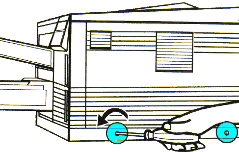
5. Remove the plastic side panel by sliding it to the right.
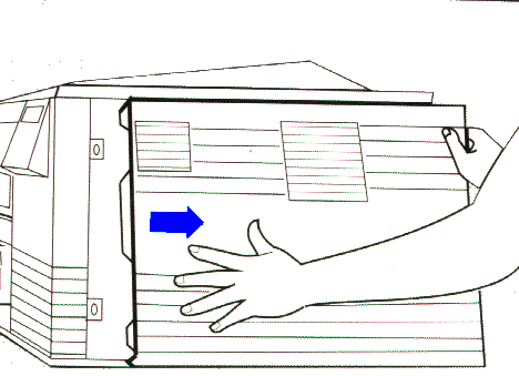
6. Because static discharge can damage the SIMM board, attach the antistatic wrist strap to the metal cover plate.
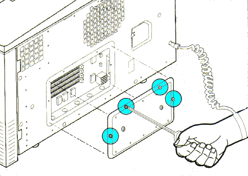
7. Unscrew the 4 screws from the metal plate and remove it.
8. Through the open panel, you can see the four SIMM board slots.
9. When inserting boards, position them from the lowest available slot to the highest slot, installing a PostScript board in the lowest available slot, then the Flash SIMM, then the RAM memory boards, from largest (in lower slot) to smallest capacity (in higher slots).
CAUTION
Touch the antistatic package or any bare metal area on the printer before removing a board from the antistatic package. Avoid flexing the board or touching components.
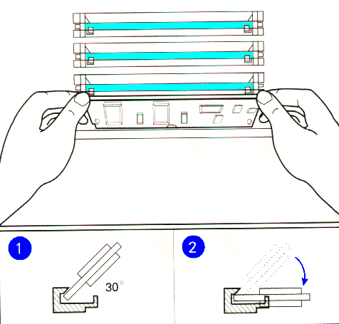
10. Remove the board from the antistatic package. Hold the board with your forefingers on the edges next to the holes and your thumbs against the edge on the back, as shown below. Orient the PostScript or memory SIMM board so the notch is on the left side.
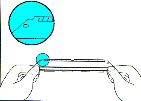
11. Hold the board at a 30-degree angle and firmly push it with your thumbs into the slot as shown below. First, push the board into the back of the slot to fully seat it. Then rotate the board down until the clips on the edges of the slot snap into place (you will feel and hear a "click"). (Illustration shows the angle of the board during insertion and shows horizontal placement when seated.)
12. Gently move the board back and forth; if it is seated correctly, it will not lift away from the slot. If it lifts up, the SIMM may not have latched into the slot. Try again.
13. Replace the metal cover plate. Do not replace the plastic side panel until after you test the board.
14. Remove the antistatic wrist strap.
Contact Us | Privacy Policy | Return Policy
